Most inexperienced computer users believe that connecting the front panel of the computer case, which contains the power and restart buttons of the computer, as well as USB inputs and audio outputs, to the motherboard is a difficult and difficult task.
But, as often happens, after spending 5 minutes studying the issue, everything becomes clear and very doable. In this article, we will look at the sequence of steps that must be followed to successfully and correctly connect the front panel to a motherboard, be it a motherboard from Asus, Gigabyte, Asrock, MSI, or others.
Step 1 - find the cables going from the front panel to the mat. board
These are the same cables that we will connect to the corresponding connectors on the motherboard. The peculiarity of these same loops, by which they can be found among other wires in the case system unit these are the inscriptions on the ends of their connectors:
- Power SW (PWRBTN) -;
- Reset SW (Reset) - Reset button;
- HDD LED (IDE LED) (HDLED) - activity indicator hard disk;
- Power LED (PLED) - Indicator of turning on the computer;
- USB1..USBn - USB ports on the front panel;
- Speaker (SPK) -;
- AUDIO (Mic, SPK L, SPK R, GND) (AAFP) - Headphone and microphone outputs to the front panel.
System unit front panel connectors
For those whose Power LED consists of 2 chips for 2 and 3 pins (as in the figure above), the rationale is as follows: on some motherboards, the POWER LED connection connector (computer power on indicator) is made on 3 pins (the middle one is not used ), and on some two. Therefore, in your case, you need to use either one Power Led chip or another.
Step 2 - find the pins on the motherboard for connecting the front panel
It is worth noting that the connection, reboot, the hard drive indicator and the computer power on indicator, as well as (F_Panel) are one group of connectors (1 in the figure below), the connection of the front USB (USB) is another group (2 in the figure below) and connectors headphones with microphone (AAFP) - the third (3 in the figure below).
On the motherboard, they are located something like this:
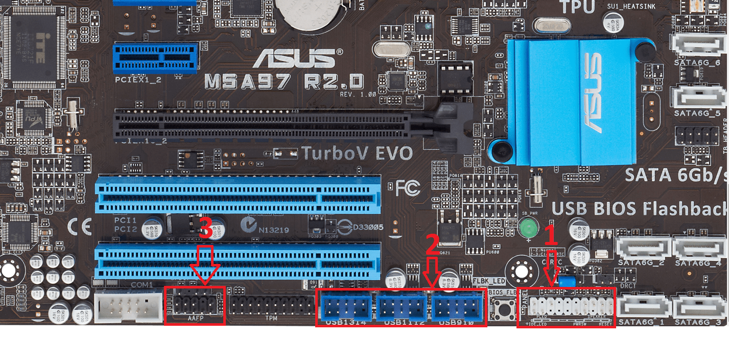
Location of connectors on the motherboard for connecting the front panel of the system unit
Step 3 - Connect the front panel connectors to the corresponding connectors on the motherboard
Option one
On your motherboard, all the contacts are signed and you simply put the chips on the contacts, observing the corresponding names and polarity. Polarity is important for HDD LED (IDE LED) and Power LED. On the board, the positive contact is signed as "+", and on the chip, the positive contact is a colored wire (different from white and black). Or if all the wires from the front panel are black, then a "+" will also be signed on them.

Polarity + and - when PLED and HDLED are connected
Even if you mix up the polarity, then nothing terrible will happen. It's just that when you turn it on, the power button will not light up and the activity LED will not blink. In this case, simply turn the non-working chip upside down on the mat contacts. boards to reverse the polarity.
Option two
The contacts on the motherboard are not signed, as in the photo below.

Unsigned front panel connection pins on motherboard
In this case, you need to find it on the Internet and look at the documentation on the pinout of the contacts of buttons, indicators, usb and sound outputs.

Last time we examined the main criteria by which it is necessary to select computer hardware. And now, having in stock all the necessary components, you can proceed directly to the assembly of the computer. Be careful, take your time and do everything carefully. Read the accompanying instructions carefully.
Prepare your workplace. It should have enough free space for all the details and good lighting. As for the working tool, all you need is a Phillips screwdriver. The assembly must be done on a non-conductive surface. Avoid build-up of static electricity. If your body is electrified, touch a metal object to discharge it. Now you can start.

Installing the processor and cooling system.
Let's start by installing the processor. Find the connector (socket) for it in the form of a rectangular shape on the motherboard.

Depending on the manufacturer of the processor (Intel or AMD), the connector on the motherboard for it can be of two types:

In our case, the Intel processor and the corresponding type of socket in the motherboard (LG-115).
Before installing the processor, you must remove the cover that covers the socket.
There is a lever on the side, lower it down with light pressure and move it slightly to the side.

Then, lift this lever up, which will open the pressure cover.

Now we take the processor and install it in the socket. There is no need to make an effort. For installation in the correct position, refer to the butt cutouts. Intel has them in the form of semicircular notches on the sides, AMD has beveled corners.


We close the clamping frame (the protective cap on it should fly off at the same time, it can be thrown away).

Let's move on to installing the processor cooling system.
Depending on the model and type of cooling system, the way it is mounted on the motherboard may differ. As a rule, it comes with detailed instructions on its assembly and installation. Therefore, we advise you to first study it and strictly follow the order of the indicated actions.
Below we will look at the most common ways of attaching a heatsink to a motherboard.
In our case, there are four holes on the sides of the processor socket.

Together with Intel processor there is a cooling system containing four legs for fastening, which must be inserted into these very holes. To fix it, you need to click on them from above.

In motherboards with connectors for AMD processors, the standard cooling system is fixed with two screws.

Let's go back to our motherboard. If you decided not to use the radiator that came with the Intel processor, but purchased a more advanced cooling system, then, in this case, a special additional frame is used to fix it, which is attached to the back of the motherboard.

It is necessary to attach this frame so that the holes on it and the board match. Then insert the screws into these holes (you will find them in the kit with the heatsink) and screw the screws onto them (on the other side of the board).

After applying thermal paste to the processor (see below), fix the heatsink with a special clamping frame and tighten with nuts on the previously installed screws.

Thermal paste application.
The heatsink may come with thermal grease already applied to it, in which case skip this step. If you have a separate tube with it in the kit, then you need to apply it yourself.
Squeeze a small amount of thermal paste (about the size of a pea) onto the processor surface

Spread it evenly over the entire surface. To do this, it is convenient to use a plastic card (be sure to make sure that the thermal paste does not flow out of the processor edges).


Now you can install the cooling system (see above).
It remains to connect the power supply of the fan (installed on the heatsink) to the motherboard. Finding this connector is not difficult. It is located next to the processor socket, has four pins (pins) and is often labeled "CPU FAN".


If the power cord has only three pins at the end, plug it in without fear into the specified connector anyway.
Installing RAM.
The RAM slots are located close to the processor. In our case, there are four slots (two black and two blue).

For the best system performance, it is necessary to install the memory sticks in pairs so that they work in dual channel mode. Those. if you want to install 4 GB, then you should purchase two 2 GB sticks. If the ultimate goal is 8 GB, then respectively you need to take two 4 GB memory. They must be installed in one bank (meaning slots of the same color).
You can see detailed instructions for installing RAM into slots in our previous article "How to install RAM on a computer", starting from the third point.
Preparing the case.
The motherboard and all other components are housed in the case. So let's get down to preparing it.
The first thing to do is remove the side covers.
Depending on the model of your case, the fastening of the covers can be very different. The most common are latches (they need to be gently squeezed out) or screws located on the back (unscrew them and pull the cover towards you). We have just the second case when the side covers are fastened with screws (top and bottom).


Inside the case of the system unit, you will find some hardware components. Typically, this is a power cord, a bag of mounting screws, and an instruction manual. Take them out. Do not touch the wires that go from the front panel (we will deal with their connection later). As a result, the case is ready for further assembly and will look like this:

Installing the optical drive (DVD drive) and hard drive.
A special rack with compartments of two types of width is provided in the front part of the case of the system unit. This is where hard drives, optical drives, and card readers are installed. In the side walls of the rack, you will find holes and slots for attaching these devices with screws and special clamps.
Let's start by installing a DVD drive. Let's place it in the topmost compartment.
Remove the front cover and slide the device from the outside into the compartment. Align all four holes (two on each side) at the unit and the sides of the rack. Secure with screws.

In the middle there are compartments for another type of device.
Previously, they housed three-inch drives, but they are now morally outdated. Therefore, today this compartment is used for card readers (memory card readers). Installing them is the same as installing a DVD drive.
At the bottom there are bays for installing hard drives. The hard drive is mounted as in the case with an optical drive, but unlike the latter, HDD is inserted into the compartment not from the outside, but from the inside of the case.

That's all. We will continue the further connection of the hard disk and optical drive below, in the section "Connecting SATA cables" and "Installing / connecting the power supply". In the meantime, let's start installing the motherboard.
Installing the motherboard.
Place the housing with the right side down.
Your motherboard should come with a rectangular bar with various holes for board connectors, which are used to connect external devices such as a monitor, speakers, keyboard, mouse, etc. It looks like this

The installation of the strip must be carried out from the inside of the case.
Position it so the holes line up with the connectors on the motherboard.

If you look at the strip from the front side in a horizontal position, then on the left there should be one (maximum two) round holes for connecting a mouse or keyboard, and on the right there should be round holes (from three to six) with a smaller diameter for a sound card.
Insert and install the strip into the rectangular cut-out, pressing on it until you hear a characteristic click, which means that it is in the grooves.

To secure the motherboard, a large metal plate with holes is provided in the case, into which special brass stands (legs) must be screwed. In the future, the board is screwed to these racks.

However, the legs do not need to be inserted into all holes, but only into those that correspond to the holes made in the motherboard. To understand which holes in the case you need to use, take and attach the board to the mounting plate of the case (when choosing the correct position of the board, be guided by the correspondence of its connectors to the previously installed bracket).


Note the location and number of the matching holes. Remove the motherboard and screw the rack cases into these places.

Place the board back in and secure it by screwing the screws through the holes in the racks.
Connections of buttons, LEDs and connectors of the front panel of the case.
Let's now connect the wires from the front panel of the system unit to the motherboard.


It will not be difficult to connect them correctly, since all wires and connectors for them in the motherboard are signed.
PWR_SW(or POWER SW) - button to turn on the computer.
RST (RESET SW)- restart button.
H.D.DLED- indication of hard disk activity
SPEAKER- Built-in speaker housing (speaker) for system warning sounds.
PLED- power light bulbs.
There are also two more cables required to be able to USB connection and audio connectors from the front of the system unit.
On the motherboard, all connectors for these cables are located in one row from the very edge.


With USB and AUDIO, we think everything is clear.
SYSTEM PANEL is designed to connect cables of power buttons, computer restart, indicators and speaker. They are signed similarly to the connectors of the cables that must be connected to them.

In some rare cases, the connectors on the motherboard may not be signed. Then we recommend using the instructions (user manual) for your motherboard model. There you will find a detailed description of the purpose of all groups of connectors and contacts.
Connecting SATA cables.
Together with motherboard you will find SATA cables. They are required to connect the hard drive and DVD drive to the motherboard.

We insert one end of the cable (with an angled shape) into the connector of the device, and the other into the connector of the motherboard.


On the motherboard, the SATA cable connectors are usually located in the lower right corner. You can recognize them by the L-shaped connectors surrounded by a frame.

They can be painted in different colors, which indicates different bandwidth speed. In our case, SATA connectors are marked in blue, providing a data transfer rate of 3 GB / s, and white - 6 GB / s. Connecting to the 6 GB / s connector makes sense today only if you are connecting a solid data drive (SSD).
Installation / connection of the power supply unit.
The place for fixing the power supply is located in the upper rear part of the system unit. You will see a large rectangular cutout.

This will serve as a guide for you to install it inside the case. Secure the power supply with the screws in the four holes.

Now let's start connecting all devices to it. Let's start by connecting the required wires to the motherboard.
The largest 24-pin cable connector (ATX Power) is responsible for supplying power to the motherboard.

For compatibility with older motherboards, it can be split into two parts (20- and 4-pin).

Finding a connector to connect it is not difficult, because it's just as big. As a rule, it is located near the RAM slots.

The second is to connect the 8-pin cable for additional processor power.

The connector on the motherboard for its connection is located near the processor.
And the last thing left for us to connect is the SATA power cables for the hard drive, optical drive, SSD.

Installing a video card.
To install modern video cards on the motherboard, use PCI Express x 16 connector.
The PCI Express x 1 slot is intended for sound cards, wi-fi adapters, etc. You can also find the old type of PCI slots. It can still be used to connect network and professional sound cards.
We hope that you have purchased a modern video card, and therefore the PCI Express x 16 slot will be of interest to us.

If in your case, like ours, there is more than one connector of this type, then use the one that is closer to the processor heatsink.
Remove the caps from the back of the case opposite the connector into which you will insert the video card.

Insert the video card into the connector slot by gently pushing down on it.

Fasten the end of the board closer to the back of the case with the screw.

The video card we installed has two connectors (6- and 8-pin). It is necessary to connect the appropriate cables from the power supply to them.

So we have finished the installation and connection of all components inside the case.

Put back the side covers, plug in your monitor, keyboard, mouse and your computer is ready to go. All you have to do is install your preferred operating system. If you have any problems at this stage, then we advise you to read our following articles:
Now, armed with the knowledge gained, you can always replace failed components in the future or upgrade your computer yourself.
Hello guests and frequent visitors to my blog;).
Have you decided to build your own computer? Or, on the contrary, at first they disassembled, because the ports in front of the system unit did not work, and now you want to return everything back? You have come to the right place. Here's how to connect the front panel to your motherboard.
I do not advise you to skip this article in the belief that you will do everything right without it. Of course, this does not apply to professionals, although in this case, mistakes are not uncommon.
Why?
The fact is that the process not only seems simple - it is. However, it assumes one important nuance - the assembly sequence. If it is not observed, some ports may not work.

Also, those who collect the system unit for the first time may get confused in the abundance of wires. Not literally, although who knows. So I recommend that you not only read my publication to the end, but also arm yourself with instructions for your motherboard. The port locations are usually the same on all models, but sometimes the labeling of the connectors is different, which can be confusing.

No manual on hand? Find it on the internet. If this did not work out either, then carefully follow the steps described in this article, and, I think, you will succeed.
Assembly guide
As already mentioned, you need to collect sequentially, so I will split my manual into several blocks. This way you will definitely not get confused.
Indicators and buttons
The lights for turning on and restarting the computer, as well as the node with the buttons, are connected first. These elements are located on one cable, from which separate connectors of different colors come out. They can also be called differently, depending on the model of your hardware. But the designations are usually similar, so you can easily figure out what's what.

What contacts are we dealing with?
- POWER SW (PWRBTN) - belongs to the computer start button;
- D.D.LED (+ HDLED) - hard drive indicator, which is constantly blinking;
- RESTART SW (RESET) - responsible for the reset button;
- Power LED + - - Power button lamp
All these wires are connected to one port located in the lower right corner of the motherboard. It can be written "F_PANEL" or "PANEL". Also, hints on what to insert where are usually spelled out. But just in case, I am attaching a photo.

You will also need to connect a small speaker - SPEAKER, which beeps when you turn on the PC or in case of system or hardware errors. Usually a separate 4-pin port is allocated for it, but it happens that it is inserted together with the above connectors.
USB
Now let's move on to the front USB connection. His contacts are similar to the previous ones. But the situation is simplified by the fact that they are connected in one plug and you do not need to insert each one separately.
A place for them is reserved at the bottom of the board and is labeled as F_USB1, 2. There can be several ports for these connectors. It doesn't matter which one you connect them to. The only caveat: USB 3.0 and 2.0 plugs are slightly different. The third revision is wider and with more contacts.

Audio connectors
It's time to plug in the sound. The cable is similar to usb-shny, that is, the connectors are also combined into one plug. The port for them is usually located next to USB and is designated as AAFP, AUDIO, A_AUDIO.

You will have an “HD Audio” or “AC 97” cable (if you don't have a discrete sound card). If after plugging it in, the headphone or microphone jack does not work, check the front audio panel settings in the BIOS. It happens that the system has the "AC97" driver, but "HD Audio" is installed in the BIOS. Set the correct parameters.

In principle, everything, there is nothing complicated here :)
Subscribe to updates.
I will be very happy to see you as often as possible on the blog pages.
Since the birth of Windows 7, almost all users have problems with no sound from speakers or headphones on the front audio panel, and the microphone does not work.
It is quite convenient for users to connect headphones or a microphone in front, for example, to communicate via Skype. At the same time, there is no need to flatter under the computer and look in the back of the system unit, among the heap of wires, for a headphone jack, pulling out the main speakers. Yes, and the length of the wire sometimes may not be enough for the headphones to connect them from the back of the computer.
As a result, the front panel remains an indispensable addition to the computer.
The lack of sound from the front panel can be due to a number of reasons:
- The front panel is not plugged into the motherboard.
- Sound card driver not configured (for Windows 7, 8, 10).
- Audio driver not installed.
- The audio driver is not compatible with the sound card.
Connecting the front soundbar to the motherboard
Open the side cover of the system unit and look for the front (front) panel connector on the motherboard - Fig. 1.
Pay attention to the absence of one pin in the connector (marked with a small red square).
Likewise in the cable plug soundbar also one hole is missing - Fig. 2
Figure 2 - Front panel plug. Red square indicates no hole
This is done so that it is impossible not to correctly connect the panel. Be careful when connecting the connector, orienting it correctly, according to Figures 1 and 2, so as not to bend the connector pins.
So. We have plugged in the connector.
We connect the headphones to the panel. Turn on your favorite song. The turntable is playing. But there is still no sound.
Setting up an audio driver using the example of the manufacturer Realtek HD
If there is no sound from behind, then the driver is simply not installed in the system or is damaged (for example, due to viruses).
How to find out the firm and driver version will be described below.
If there is sound from behind, but not from the front, then we adjust the driver.
NOTE: In the operating room Windows system XP front panel audio issues were missing. The sound card driver did not have to be configured.
Open the sound card manager Fig. 3.
Figure 3 - Realtec HD Dispatcher (brown speaker)
A large window appears in Fig. 4, in which, according to the arrow, click on the icon.
Figure 4 - Click on the yellow icon
Then we get into another small window, where we put a check mark as in Fig. 5.
Figure 5 - put a check mark as shown
Congratulations!!! Now our panel is working.
Setting up a sound driver using the example of a VIA sound card
Setting up the VIA audio driver is almost the same as setting up the Realtek HD driver. It's just that the front panel settings are located a little differently in the program interface.
We open software sound card Fig. 6.
Figure 6 - Window of the VIA sound card settings program
Click on the icon indicated by the arrow in Fig. 6, and we get into the window, where, according to Fig. 7, install the switch.
Figure 7 - Select the item marked with orange highlight
The front panel audio settings have been successfully completed. Plug in your headphones and enjoy the sound.
If there is no Realtek HD Manager or VIA. What to do?
The absence of the Realtek HD Manager or VIA program is, if your computer has unofficial version audio driver.
Often with Windows installations 7 sound driver, on many motherboard models, is automatically selected operating system and is compatible with sound chip. However, the settings program itself (Fig. 4 and 6) is not installed. In this case, the front panel cannot be configured. At the same time, all ports in the rear panel work perfectly.
To download required driver for your sound card, we need to find out the manufacturer of the sound chip and its model.
This can be done using the Everest program.
Download the program as shown in Fig. eight.
Figure 8 - Downloading Everest
This is a portable version that does not require installation. Open the downloaded archive and run the everest.exe application. The program window will appear Fig. 9, in which you can learn a lot of useful and interesting things about the hardware of your computer.
Figure 9 - Everest program interface
But we are still interested in how to find out the model of our sound card.
We do everything as in Fig. 9 - open the item "Multimedia", and then the sub-item "Audio PCI / PnP". If in this sub-item you see a blank window, then select the sub-item "HD Audio".
On the right side of the program, we see a list of audio devices. It may differ for you both in quantity (there may be only one sound device), and in name.
We are interested in the device marked as in Fig. 9 - Realtek ALC 888. This is our sound card. It is on it that we will look for the required driver, according to the name.
On the Internet, by searching for Realtek ALC 888, or for example Realtek662, depending on which sound card you have, you can find a driver with a settings program for it.
In order not to look for a driver for a specific model, I give you a link to a universal audio driver installer that fits almost all models of Realtek sound chips.
If you are the owner of a VIA sound card, you can download the driver with the program for this audio card on this site.
Connecting the front panel to an additional sound card, for example, ASUS Xonar DX 7.1
Figure 10 - Sound card ASUS Xonar DX 7.1
Owners of additional sound cards, such as ASUS XONAR or Creative, can also connect the front panel, customize it and enjoy high quality sound in games, movies or listening to music.
If you have the front panel connected to the motherboard, then you need to disconnect its plug and connect it to the same connector of the sound card (in our example, ASUS XONAR DX 7.1) - Fig. eleven.
Figure 11 - Connector for the front panel of the ASUS Xonar DX 7.1 sound card
Connect the plug to the connector, in the same way as to the motherboard and also align their pins with the holes.
Figure 13 - Application for setting the sound, as well as the front panel
The sound settings program will open in front of us. fourteen.
Figure 14 - Setting the sound for headphones
Expand the "Analog Input" list and select FP headphones.
(the computer is facing you). On the motherboard, look for small yellow or blue connectors, usually at the bottom.
Each such connector has two rows of pins (needles): in one row there are five, in the other four. Let's call the left or right side of the connector, where both pins are located, side "A". The second, with one pin - "B".
The five pins, starting from the "A" side, are labeled as follows (in series): VCC1 + 5V, Data -, Data +, Ground 1, NC.
The last pin - NC - is not used.
The four pins of the second row, starting from side "A", are labeled as follows (in series): VCC2 + 5V, Data -, Data +, Ground 2. There is no fifth pin (pin) in this row.
Examine the connector on the end of the ribbon cable coming from the USB port. It should be labeled: VCC1, Data 1 -, Data 1 +, Gnd 1. The labels may differ slightly, but it's easy to figure it out - on the first socket under the pin, VCC or +5 V is always indicated, the last is Ground or GND.
In most cases, connector wires are in standard colors:
+ 5V red
Data - white
Data + green
GND black
Connect the connector from the USB cable to the socket on the motherboard to the row of five pins. The first - from the "A" side - must be connected to VCC1 +5 V. The fourth - Gnd 1. The last fifth pin remains free. There is no pin next to it in the second row.
To simplify the connection, special adapters can be used to exclude the possibility of incorrect connection. They are suitable for connectors on the board, usually blue, with a small side and a key and allowing you to connect the adapter in only one way.
The pins on such an adapter are designated as + 5V, P2-, P2 +, GND. If you have such an adapter (they can be supplied with the motherboard), connect the ribbon cable to it in accordance with the marking, then insert the adapter into the socket on the motherboard.
By connecting all USB ports, close the side cover. If you are still not completely sure of the correct connection, then after turning on the computer, connect a USB mouse to the front port. If it works fine, then everything is connected correctly and you can safely connect flash drives and other equipment.
Sources:
- how to connect the front
When buying a computer, a beginner - someone who has little understanding of the PC in general - needs some help in assembling and connecting this device. If it is not possible to call a specialist or friend, then this instruction will come to your aid.
You will need
- Connect all interfaces and loops in the correct order.
Instructions
Take the main cable for the system unit from the mains. There will be a plug on one side and a trapezoidal connector on the other. It is necessary to turn the system unit towards you with the back (back) side, many connectors of the "female" and "male" types. We take the power cord, on the side of which there is a "female" connector, and connect it to the "male" connector located in the upper part of the system unit. Do not connect it directly to the network.

We put it next to the system unit to connect the monitor to the system unit. For this we need the same mains power cable. The principle is the same, only now we connect the cable to the monitor. We also do not connect it to the network.
We take the next cable - to connect the monitor and the system unit (VGA cable). We connect one side to the monitor, the other to the system unit, first you need to find the VGA connector on. After connecting this cable, tighten the plastic bolts with your fingers or a small screwdriver. This is necessary for a constant and stable signal.

The keyboard and mouse connections are very similar. The only difference is the color of the plugs and jacks for these devices. The keyboard and mouse jacks (PS / 2) are located below the power jack of the system unit. The keyboard is lilac and the mouse is green.
Recently, they began to produce devices under the USB interface. In this case, everything is much simpler. You need to insert the plug of the device (or mouse) you need into the USB port.

The last stage of connection will be the speakers and the system unit. There are 2 cables leaving the main speaker - a power cable and an audio cable. We need to connect the audio cable to the system unit. We find a round green socket on the system unit and.
Now we need to connect all the power cables to the outlet. You can use (pilot) here. After connecting all the devices for the system unit to work, we need a computer by pressing "Power" on the front panel.

If you turn on the computer, but there is no image or no sound, then something was wrong. We advise you to seek help from people who are well versed in this matter.
Sources:
- system unit connection
- Types of peripheral devices and rules for their connection
If you have not bought a separate sound card or you don’t Personal Computer, but a laptop, you may need to connect sound from the sound card built into the motherboard. On modern motherboards, such built-in sound fees have reached such a level that they are almost in no way inferior to discrete sound solutions. Even support for 8-channel audio from integrated audio solutions is no longer something special.

You will need
- - Computer (laptop) with Windows OS;
- - motherboard with built-in sound card;
- - drivers for the built-in sound card;
- - sound speakers.
Instructions
First, install the drivers on the built-in sound fee. Find the disk that came with your motherboard, it should contain everything you need, including these drivers. Installation of sound drivers happens almost automatically - just insert the disc into the drive, click the line responsible for their installation, and follow the instructions on the screen. The installation wizard will ask you to accept the terms of the license agreement, agree with them, click "Next" and wait until the installation is complete, then restart your computer or.
After Windows boots up, wait while the system detects a new device (that is, your sound card) and install drivers on it. Eventually, a message should appear stating that the device is installed and ready to use.
Plug the speaker wire into the audio jack fees... If these are stereo speakers, you only need to connect one wire. If it is a 6- or 8-channel audio system, there may be several wires. If you have a computer, the audio connectors fees usually painted. Green or light green color marks the input for stereo speakers and center speakers in the case of a multichannel audio system. There shouldn't be any problems finding the right connector, just plug in the appropriate wire. In a multichannel audio system, all the wires that connect to the sound card are usually colored the same colors as the connectors on the sound card.
If you have a laptop, the audio connector fees can be of any color. In order not to be mistaken, refer to the user manual, or you can turn on and alternately insert the plug into several connectors on it until you hear a sound. There is no need to be afraid that you will insert the plug into the wrong connector, as this does not harm the operation in any way.


